
A common problem faced when doing electronics with a platform like the Raspberry Pi (or Arduino, or other similar platforms) is the limited number of inputs and outputs. It doesn't matter how many the platform provides, there is always a need for more. Even on the Raspberry Pi with its generous seventeen GPIO pins (more if you're using the new model B+), you can always come up against situations where you've run out of outputs but still need a few more.
There are various ways of getting around this problem, including specialized output expander boards, but there are at least two relatively simple solutions that can be easily expanded. One is using shift registers, which are discussed on a separate page, but here we'll look at demultiplexer chips.
Let's start with the name, what does it mean when signals are "multiplexed"? Basically it combines several signals, which are either on or off, into a smaller number of coded signals. So for example if you have eight signals coming in, and you know that only one of them is "on", then you've only got eight possible states. You can reduce the number of wires required to carry these eight possible states by "multiplexing" those signals into just three bits. If wire 1 is on, you call that a 0 and set the three wires to "000". If wire 2 is on, you call it a 1 and set the three wires to "001", and if wire 8 is on, you call it a 7 and set the three wires to "111". In this way you've combined your eight signals together and now only need to transmit three, which can be very useful for a variety of reasons.
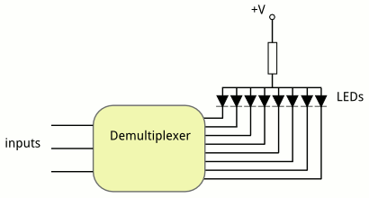
What's that got to do with our GPIO outputs? Well, we can do the opposite, treating the GPIO outputs as being already multiplexed, and using a demultiplexer to separate just three GPIO outputs into eight output signals. So with just three outputs from the Pi, I can switch any one of eight LEDs on.

An example of a single demultiplexer, lighting one of eight LEDs using three pins.
This example has the selected output going low, sinking current through one of the LEDs.
On the face of it, that doesn't sound terribly impressive, you only gain five outputs and you've got the awkward restriction that only one of those outputs can now be on at any one time. But there are times when that restriction is no problem, and as we'll see shortly, you can use more than one demultiplexer to gain much greater advantages.
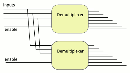
We've seen that with three GPIOs and one demultiplexer, we can control eight outputs. Obviously we can use two separate demultiplexers, with six GPIOs and two demultiplexers to give sixteen outputs, but that's not too clever. Instead, we can use the same three GPIOs as inputs to both demultiplexers, and use two further GPIOs to enable or disable each of the demultiplexers. So now we're at 5 GPIOs, 2 demultiplexers, and 16 outputs.

An example of a pair of demultiplexers, controlling 16 outputs with 5 pins.
Can we do any better? What if we had three demultiplexers? With one extra GPIO to enable the third demultiplexer, we've now got 6 GPIOs multiplied up by 3 demultiplexers to give 24 outputs. Not bad, but still not very clever.
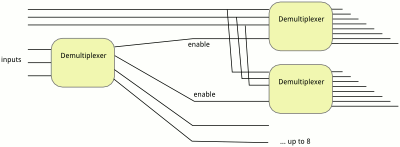
Things get cool when we cascade these demultiplexers, so the output of one demultiplexer controls another. This starts to make sense when the number of outputs to control gets higher. In this way, very large numbers of outputs can be controlled with just 5 or 6 pins.

An example of cascading demultiplexers, controlling up to 32 outputs with 5 pins or 64 outputs with 6 pins.
This diagram shows the first demultiplexer enabling and disabling up to 8 further demultiplexers, giving up to 64 outputs controlled by just 6 GPIO pins.
One example of a chip which works in this way is the SN74LS138N. This is cheap and popular, and available in an easy-to-use 16-pin DIP package. This particular example has the property that all the output pins are high except one which is low. So LEDs can be connected from +V to the output (as shown in the first diagram above) rather than from the output to ground. Some other demultiplexers may work in the opposite way.

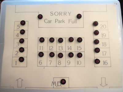
An example of LEDs switched by demultiplexers, controlled by the Raspberry Pi.
This is one example of an LED display where the restriction of one output active is not a problem - there's just one part of the display to indicate so the demultiplexers are perfect for the job. This lunchbox-based project wasn't originally created for the Raspberry Pi, but the Pi has now given it an (unexpected!) second lease of life ;)