
This is a simple electronics project to get used to the components and practice soldering components together. It comes in kit form with full instructions, and the instructions are even available online as pdf so you can see what's involved.
The kit is manufactured by velleman.eu, and further details about this "running microbug" can be found on their product page (if they haven't moved it). The company has a wide distribution network so it will probably be better to get it from a local distributor rather than direct from velleman.
It's all just analogue electronics, no chips or software. It's a simple circuit using transistors, resistors, LEDs and photodiodes. Two motors drive the bug forwards, and the back is just held up by a roller. But the effect is clever - the circuit is built in two independent halves, each half just driving one tiny motor according to the light received by its photodiode. But then how does it steer? Easy - if the photodiode on the right side detects light, it drives the motor on the left side of the bug. If the photodiode on the left side detects light, it drives the other motor. So just based on the relative amounts of light received on the two sides, this bug can steer itself so that it points towards the light. Clever. Even without a 'brain', or any central component deciding whether to turn left or right, actually with no decision making being done at all, this bug acts like something alive and appears to be 'interested' in the light, seeking it, guided by it.
In the UK you can get it from Maplin for 10 GBP. Just search for "microbug" at maplin.co.uk or try this direct link. If you're in Zürich you can check out the shop Pusterla which has the kit in-store.
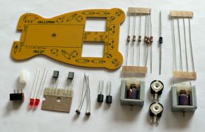
The microbug kit contents laid out
The kit, as shown on the right, includes everything you need to build the bug, except:
Everything else (the main board, the battery holder, the motors, wires, and other components) all come in the box. If you have additional tools like solder suckers, component holders, continuity testers etc then you can for sure use them but they're not really necessary for a basic kit like this.
First thing to do is work out where you're going to build it. Prepare a flat area large enough to work on, lay out some newspapers or something if you're using a table you like, make sure you've got a power point nearby for the soldering iron, and try not to start 10 minutes before the table is needed for dinner ;)
Next, unpack the box and check that you've got everything you need. Lay all the components out and check you've got the right numbers of everything. Check that you know what each piece is and what the instructions call it. There is labelling on the board to help with the codes. Note that in this particular kit, the two halves of the circuit diagram are exactly the same, so only one half is shown in the instructions. So if you're wondering why you've found four transistors but only two are shown in the circuit diagram, now you know why!
The instructions are fairly diagrammatic and take a little bit of figuring out but that's part of the fun. They take you step by step, first soldering the easy stuff (like resistors), then the components with polarity (like LEDs), and then the slightly trickier stuff (like the motors).
In this kit they use an odd technique to mount the motors at an angle - they abuse the metal case of the mini motors and form a mechanical joint with solder. This is fine for a small model like this but holding and soldering such an odd joint is a bit fiddly. That's about the only part you should have trouble with though, as long as you don't use too much solder, and make sure you apply the solder to the component, not to the iron. You can find instructional videos at instructables.com and makezine.com for basic soldering technique if you're not sure.
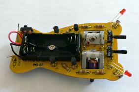
The completed microbug ready for testing
Set the two potentiometers on the front to about the middle of their range. Plug in two AAA batteries (taking care not to twist the battery holder too much) and switch on in a not-too-bright environment. Now you can try shining a torch in its "eyes" or covering up one photodiode and taking it near a lamp. Each photodiode should control one motor, and the corresponding LED should light up.
If it doesn't work, then it's time to do some debugging - first of all just check by eye whether the solder joints look tidy or not. Does one half of the bug work but the other not? Is a contact broken (in which case, resolder it) or are there crossed tracks where there shouldn't be (in which case, try to remove the unwanted bridge).
It runs pretty fast for a little thing, so you'll need a fairly large flat area to test it out. Actually it would be nice to slow it down a bit, but that can be left as an extension project!
The last thing to do is go right back to the start and check out the circuit diagram again - now that you've built it, and it works, see if you can figure out how it works - what do the transistors do? What do the photodiodes do?