

Up until now, the electronics which we've connected to the Pi has just been simple switches and LEDs. Now we'll get a bit more ambitious and try to connect it up to a more sophisticated sensor, a three-axis solid state accelerometer called a MMA7455.
Why would we want to do this? Well, after the success of the "steady hands" game, I wanted to try out other simple games using a handheld controller, and I thought a motion-sensitive stick would be quite cool. With a little imagination it could be turned into a magic wand, or a light sabre, or tennis racket, or fishing rod, or perhaps even a steering wheel. But I want to keep things simple, so it will still be connected by a real cable to the pi, no wireless technology here.
The accelerometer just measures acceleration in three perpendicular directions, so if it's held stationary it will measure the angle of gravity, which is the angle of the stick. Changes in the orientation of the stick with respect to gravity will then be measurable (rotating about a vertical axis won't be of course). Also, any sharp movements of the stick, or shaking, will be measurable too, as changes in the magnitude of the acceleration or changes in the direction.
If you want additional functionality, you can look for other modules which as well as an accelerometer contain a gyroscope and/or a magnetometer, but here we're just interested in the accelerometer bit and the MMA7455 seems to be a popular and widely-available choice.
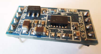
The MMA7455 comes either as a single chip (which looks extremely awkward to deal with, see the Magpi article from issue 4) or as a prepared board including 8 clearly-labelled header pins. Clearly the board is preferable, and not at all expensive. Searching for this product part may give you local options to buy one for a few dollars, or you can take advantage of ebay's worldwide supplier network, who will send you one for about two dollars including shipping from China.
The four pins on the left are labelled IN1, IN2, GND and VCC. On the right are CS, SD0, SDA and SCL.
The wiring up is very straightforward. The board has 8 pins, but we will only be using five of them. VCC should be connected to the Pi's 3V3 output (pin 1). GND should be connected to the Pi's 0V ground pin (pin 6). Then we tell the board to use I2C communications by wiring the board's CS pin high (connected directly to 3V3 or VCC). Finally we connect the board's SDA pin to the Pi's SDA pin (pin 3) and the board's SCL pin to the Pi's SCL pin. And that's it.
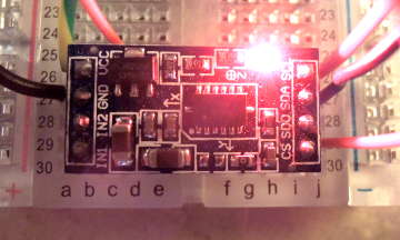
This board has a little LED near the SCL pin, which lights up red when everything is wired correctly.
This particular accelerometer uses a standard communication mechanism called inter-IC or I2C. Before the Pi can use this, we need to activate it and install the necessary packages. This is thoroughly explained in the youtube video called (descriptively enough) "How to use an MMA7455 Accelerometer with the Raspberry Pi via I2C" by Zachary Igielman.
In summary, you need to go through some fiddly steps to allow the I2C to work, as follows (based on Raspbian):
i2c-bcm2708 by editing the file /etc/modprobe.d/raspi-blacklist.conf and commenting out the line which blacklists it. (For some reason this module is blacklisted by default to prevent it from being loaded.)i2c-dev module to the kernel by editing the file /etc/modules to include a new line i2c-devsudo apt-get update and then sudo apt-get safe-upgradesudo apt-get install python-smbus i2c-toolspi user to use i2c using sudo adduser pi i2c
i2cdetect -y 1 and checking that it returns "1d" in the appropriate square of the grid (row 01, column d)Note, it could be that something has changed in the Raspbian images and that these steps to configure I2C are no longer sufficient. If this still doesn't work ("no such file or directory"), then try the instructions at adafruit, using raspi-config. Then reboot and try again.
This little testing script comes from the same youtube video linked earlier, but it looks like it was adapted from the MagPi code. I just simplified it a little.
import smbus
import time
import os
import math

# Define a class for the accelerometer readings
class MMA7455():
    bus = smbus.SMBus(1)
    def __init__(self):
        self.bus.write_byte_data(0x1D, 0x16, 0x55) # Setup the Mode
        self.bus.write_byte_data(0x1D, 0x10, 0) # Calibrate
        self.bus.write_byte_data(0x1D, 0x11, 0) # Calibrate
        self.bus.write_byte_data(0x1D, 0x12, 0) # Calibrate
        self.bus.write_byte_data(0x1D, 0x13, 0) # Calibrate
        self.bus.write_byte_data(0x1D, 0x14, 0) # Calibrate
        self.bus.write_byte_data(0x1D, 0x15, 0) # Calibrate
    def getValueX(self):
        return self.bus.read_byte_data(0x1D, 0x06)
    def getValueY(self):
        return self.bus.read_byte_data(0x1D, 0x07)
    def getValueZ(self):
        return self.bus.read_byte_data(0x1D, 0x08)

mma = MMA7455()

for a in range(1000):
    x = mma.getValueX()
    y = mma.getValueY()
    z = mma.getValueZ()
    print("X=", x)
    print("Y=", y)
    print("Z=", z)
    time.sleep(0.2)
    os.system("clear")
Just save this script somewhere on the pi and call it with python accel.py. Then the x, y and z values are shown several times a second until you press Ctrl-C to quit the program.
If you want to take this further and make it more graphical, you can look at the MagPi article mentioned earlier for tips on how to draw graphs using pygame.
It seems that the raw byte values coming out of this accelerometer are not calibrated, which means that it's difficult to compare them and calculate orientation values correctly. Depending on what you want to use the accelerometer for, this may or may not be a problem for you. For example, the graph-drawing example above only uses one axis and values between 0 and 255, so the calibration isn't too critical.
If we want to use all three axes and calculate some meaningful values like angles and magnitudes, then we're going to have to calibrate it somehow. It seems that each device has small manufacturing differences, either in the MEMS device itself or in the assembly into the finished board, and these have an effect on the offsets on each axis.
With just some simple experimentation, we can quickly identify which of the axes is which. For example, if we run the above script and rotate the board about its long axis, we can see that the X values don't change. So the X axis must be along the long axis of the board, as can be confirmed by the little "X" and arrow printed on the board. Similarly, the Y axis points across the short axis of the board, and the Z axis is perpendicular to the board.
All three X, Y and Z values are given back as single bytes, so they all can show values between 0 and 255. The first attempt to make sense of these values subtracted 128 from each value (to get values between -128 and 127) in the hope that 0 then means 0. But it can quickly be seen that calculating the magnitude of the acceleration vector using
mag = int(math.sqrt(x*x + y*y + z*z))
gives completely meaningless values. Instead, we need to look at each axis individually, and figure out what its normal range is when held statically in different orientations. I only have one of these devices so I have no clue how similar the values between devices are - I assume that what works for this board won't work for yours.
    x2 = ((x + 128) % 256) - 128
    y2 = ((y - 240 + 128) % 256) - 128
    z2 = ((z - 64 + 128) % 256) - 128
    mag = int(math.sqrt(x2*x2 + y2*y2 + z2*z2))
    vertangle = 180 / 3.142 * math.atan2(x2, math.sqrt(y2*y2 + z2*z2))
In the case of the y axis, the zero acceleration value is around 240, so 250 is slightly positive, 5 is even more positive, but 230 is negative. By subtracting 240 and adding 128, this brings the zero level around to 128, in the middle of the range where we want it. Then doing a modulus with 256 wraps everything between 0 and 256 again, and subtracting 128 then makes zero zero, positive values positive and negative values negative. Doing this for each axis makes the mag value then stable at around 64 (perhaps a coincidence), and we can then calculate the angle which the long axis makes with the vertical by using an inverse tangent function as shown.
If you really want to get into the details, there's a rather complex and mathematical tutorial from Freescale called Tilt Sensing Using a Three-Axis Accelerometer which goes into the theory and trigonometry.
It's not very useful if the accelerometer is just plugged into a prototype board, especially if the wires to the board are prone to popping out when you move the accelerometer. So we need a way to mount the board into something a bit more robust. For this I chose a short stick from the forest, with a decent length of 8-core cable which was being thrown away anyway.
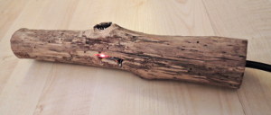
The cable from the Pi comes into the end of the stick on the right, and the accelerometer is mounted in the middle (you can just see the LED here). I also added a simple push-button into the knot at the top-middle of this picture.
The idea is that you hold the stick upright in one hand, with the cable coming out of the bottom, and the button is conveniently positioned for your thumb. Then depending purely on software, it can become any kind of movement controller, and the button can be a restart or fire or any other kind of action.
The other end of this cable is soldered onto a little ribbon cable for convenient mounting on the Pi, so you just slot the ribbon connector onto the GPIO pins. The accelerometer's pins are connected as before, and the button is connected to one GPIO pin and ground. Software configures this GPIO to be an input with pull-up, so that button presses are detected with falling GPIO input value.
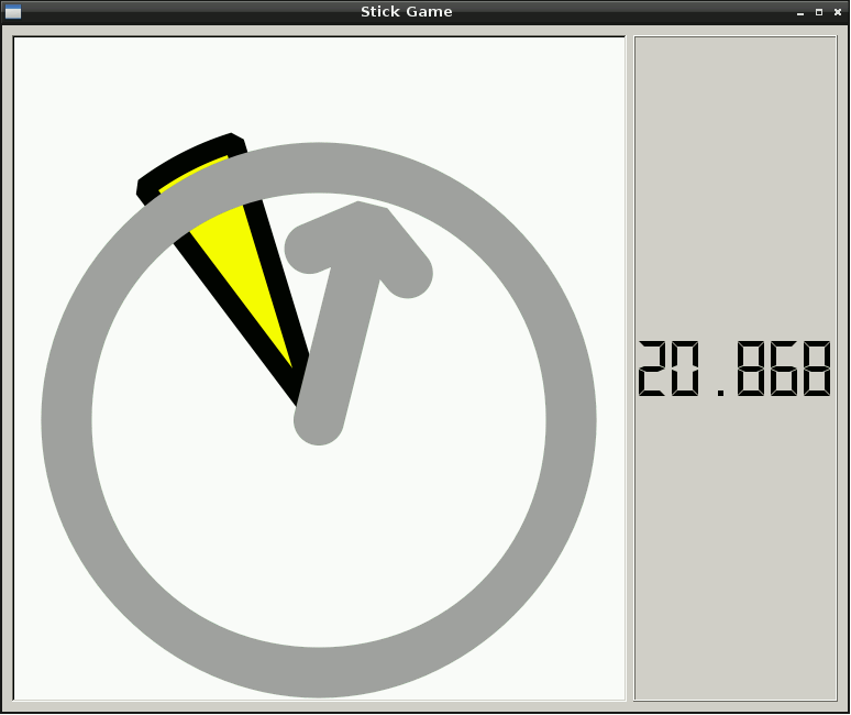
The rest is just software, so we're free to experiment with different game ideas, graphics on the tv, sound effects, etc.
This first example, shown on the right, uses python and pyqt to make simple game graphics on the tv. The yellow wedge is the randomly-moving target, and the big grey arrow rotates as the stick rotates, as measured by the accelerometer. When the arrow matches the target, the ring turns green and a rectangular blue health bar doesn't get decremented. When the arrow doesn't match, the health goes down a little bit. When the health goes down to zero, the game is over and the clock stops.
The aim of the game is to match the movement of the target as closely as possible, so that the game lasts as long as possible. The final time is shown on the right (this timer display of course borrows heavily from the one in the buzzer game).
The movement of the yellow target is random, and increases in difficulty as time goes on. The maximum target angle (deviation from vertical) increases, the maximum speed increases, and the severity of the random changes in speed increases as well, to make the target increasingly difficult to follow.
The second game is a little bit more ambitious with the graphics, and also steps up the level of gratuitous violence towards innocent aliens.
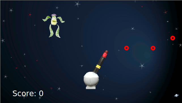


The ideas for this are not mine, and neither are the carefully-made drawings. I helped with making the gun out of lego and photographing it though, and with the programming. Again it uses python, and Qt, and QGraphicsItem objects for the visuals, and borrows the accelerometer code from the first game. The graphics run full screen on the tv.
Aiming of the gun is done by pointing the stick, and shooting by pressing the button. For shooting a green alien you get one point, and for the purple monster you get 10 points. But the purple monster takes two hits to kill it, with the first hit just one of his arms falls off. When any of the aliens or monsters get to the bottom of the screen, the game is over.
Again, the difficulty of the game increases as time goes on, in particular the probability of spawning new enemies increases, and so do the maximum number of enemies and their speeds. Sound effects aren't in there yet but are promised, and will be recorded and played back in the same way as the steady hands game.
Hopefully more such games will follow. Maybe something involving some kind of forwards striking action more like a wand, although for the safety of the stick and for the players we'll try to keep the motion simple and smooth rather than hectic and frantic.
It turns out that it's even possible to use a wireless controller such as a Wiimote with the raspberry pi, using a bluetooth USB dongle. That may even be cooler than a stick from the forest with a cable coming out of it. But I'm not sure. I don't know how much it costs to buy a Wiimote though, and have never played with a bluetooth dongle either.
For more information see TheRaspberryPiGuy's youtube video.